Interpret battery test conditions, distinguish no-crank from slow crank, and build a measured starting-system test plan.
What you will learn
Identify the actual starting complaint and battery type.
Distinguish state of charge from demonstrated performance.
Interpret loaded cable-loss and starting observations using supplied limits.
Verify the correction and document remaining uncertainty.
Before you start
Electrical Measurement Foundations is recommended. Low-voltage knowledge only; no high-voltage battery service.
How to use this workbook
Read each lesson, work through its example, then answer the practice questions before revealing the explanations. Complete the written exercise before taking the assessment. Numerical examples are fictional training data, not vehicle service specifications.
Open study guideFree lessons for anyone. Print or save a PDF copy.
Plan for approximately 20 minutes of reading and 45 minutes working the examples and exercises. Assessment time is separate.
Course material
Study at your own pace. Open each lesson when you’re ready.
Identify the complaint and safe test conditionsRead & apply
Know the components: conventional starting system
Trace the energy path and control path separately. This map covers a conventional low-voltage starter arrangement, not every hybrid or integrated starter-generator system.
Battery posts and cable clamps
Stored electrical energy leaves and returns through connections whose condition matters under load.
Positive cable and return path
Carry operating current; either path can lose voltage through excessive resistance.
Starter solenoid and motor
The switching/engagement mechanism and motor perform related but distinct functions; use the actual design's circuit information.
Control circuit and start authorization
Switches, relays and modules determine whether cranking is commanded. A no-command fault is not the same as slow cranking.
Pinion and ring gear
Mechanical engagement transfers starter torque to the engine; electrical readings alone cannot establish mechanical condition.
How the parts work together
A valid start command permits the specified switching and engagement sequence. Current through the motor produces torque. Source condition, path losses, motor condition and engine mechanical resistance all influence cranking. Identify which part of that chain the symptom and test actually address.
Identify and explain
Which path could explain a normal unloaded voltage reading but low voltage at the starter while cranking?
Check your explanation
A resistive feed or return connection may lose substantial voltage under operating current. Measure the relevant paths under the prescribed loaded condition instead of treating the unloaded reading as proof.
Separate no-crank, slow-crank and normal-crank/no-start complaints. A normal-speed cranking engine that does not run is not automatically a starter failure. Ask whether the problem occurs cold, hot, after parking, intermittently or after recent service. Record warning messages and the vehicle's observed behavior rather than relying on “dead battery” as a complete diagnosis.
Identify the installed low-voltage battery type, rating and location, along with the approved test and connection points. Some vehicles use battery monitoring, remote terminals, start-stop systems or battery registration procedures. Follow the actual application rather than assuming every vehicle uses the same charging or replacement process.
Inspect for case damage, leakage, loose mounting, damaged cables and inappropriate connections before testing. Use required protective equipment and safe work-zone practices. Do not charge or jump a battery whose condition makes that unsafe under the manufacturer's guidance. Keep sparks and inappropriate connections away from the system. This course does not provide a universal jump-start sequence.
Set the test scope and preserve relevant fault data. Unusual hybrid/EV conditions require the proper safety boundary; a familiar low-voltage battery does not authorize traction-system work.
Separate charge from ability to perform
A battery's state of charge describes available charge at that time; condition describes its ability to meet the applicable performance requirement. A discharged battery may need the specified charge-and-retest process before a valid condition decision. A satisfactory resting voltage alone does not prove that it can supply starting current. Conversely, a failed starting event does not prove the battery caused it.
Identify the installed chemistry/type, rating value and rating standard. The same number entered under the wrong standard may produce a misleading tester conclusion. Inspect accessible condition and connections using the required precautions. Damage, leakage, abnormal heat or another hazard changes the plan; a routine tester connection is not the next step for every battery presented to the bay.
Record the setup
Write the vehicle identity, battery identification, temperature context, test mode, connection points and result exactly enough to reproduce the decision. If the tool says charge and retest, preserve that instruction and the subsequent result rather than relabeling it “bad.” A printed slip with no matching battery data is weak evidence for either replacement or continued service.
Classify the starting complaint first
Distinguish no crank, slow crank and crank-but-no-start before choosing tests. A starter-circuit test plan does not by itself diagnose a running engine that will not fire. Ask about temperature, time parked, recent work, warning messages and whether the problem is repeatable. Preserve relevant diagnostic information before clearing or disconnecting anything.
Inspect the battery's physical condition and identify its type and application before using test or charging equipment. A damaged or leaking case changes the safety plan. Do not use an acceptable voltage reading to dismiss a physical hazard. Record the difference between a customer report and a reproduced condition; “would not start yesterday” is not the same as today's measured slow-crank event.
Separate starting concerns
No crankCheck the applicable command and power path
Slow crankEvaluate battery, path losses and mechanical load
Cranks normallyUse the appropriate no-start diagnostic path
IntermittentDocument the conditions needed to reproduce
Try it before reading the answer
The engine rotates normally but does not run. Is replacing the starter supported by that observation?
Worked answer and reasoning
No. Normal rotation does not prove the cause of the no-start, but it does not support a starter replacement by itself. Route the concern into the applicable crank-but-no-start diagnostic process and preserve relevant evidence.
Understand battery test meaning and limitationsRead & apply
State of charge and battery performance are different questions. A resting voltage observation may help evaluate charge state under defined conditions, but does not alone prove the battery can deliver required current. Temperature, recent charging, surface charge, battery chemistry and rest conditions affect interpretation. Use the tester and vehicle procedures rather than a universal pass voltage.
Enter the correct battery type and rating standard into an approved tester. A rating expressed under one standard should not be entered as though it were another. Poor clamp contact or wrong input data can invalidate a printed result. Record the selected settings, relevant conditions and the test instruction or result.
If the tester calls for charging and retesting, follow that direction when safe. “Charge and retest” is not the same result as “replace.” A discharged battery can be the consequence of another issue, including use pattern, connection condition, charging behavior or unwanted draw; replacement alone may not resolve the underlying problem.
Keep the actual test report with the repair order and explain its meaning without turning a limited result into a guarantee of future starting.
Describe the starting symptom precisely
No crank means the engine is not being rotated by the starting system. Slow crank means rotation occurs but is slower than expected under the relevant conditions. Crank-no-start means the engine rotates but does not run. These descriptions lead to different investigations. A customer saying “won't start” does not yet identify which one occurred.
Ask whether the condition is cold, hot, intermittent or associated with recent work. Note the sounds and indicator behavior without treating them as unique diagnoses. A click may indicate that part of a control path responded, but it does not prove every main-current connection or mechanical component is sound. For no-crank, the required command, interlock and control conditions must be evaluated through the applicable procedure.
Compare the symptom with the authorized scope. Battery testing is one check, not a complete diagnosis of every starting complaint. If a fault is not currently present, document the test conditions and uncertainty. Do not report that a hot intermittent problem was resolved solely because the engine cranked once while cold.
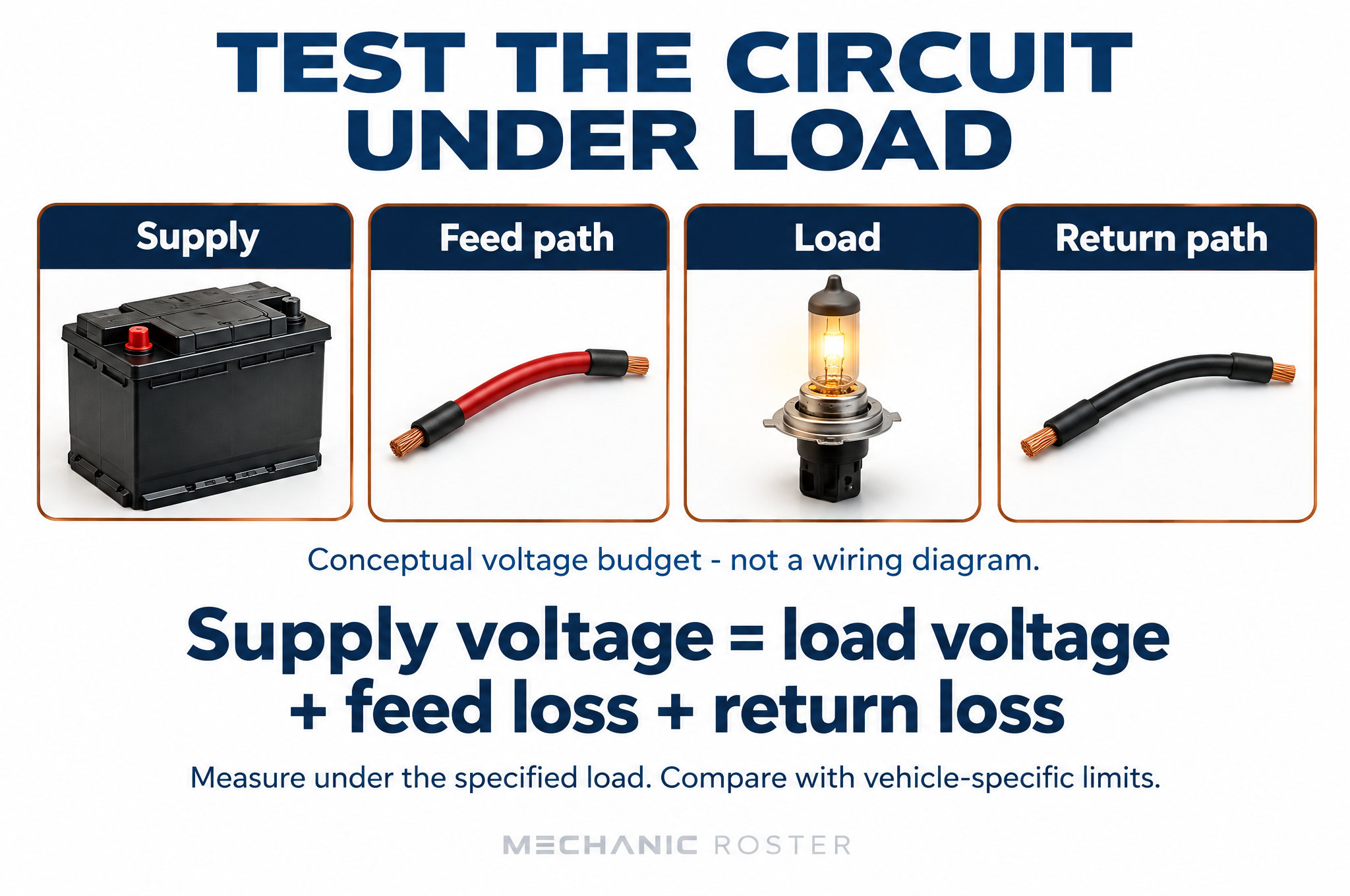
Measure circuit losses under load and compare with the vehicle procedure.
Interpret a battery result within its conditions
State of charge, test method, temperature, battery specification and equipment setup affect what a result means. “Good voltage” is incomplete without the points, operating state and reference. A discharged battery may be the consequence of another problem rather than the original cause. Distinguish the need to restore a valid test condition from a decision to replace the battery.
Suppose a fictional tester requests charging and retesting. That is not the same result as a confirmed failed battery. Follow the tester and vehicle instructions and investigate why the battery was discharged when the evidence warrants it. Repeated replacement without checking the underlying condition may leave the customer's concern unresolved. Record the final valid result rather than keeping only a convenient initial reading.
Battery voltage and starting-path losses are separate Component overview and simplified steady-DC voltage budget, not a connected wiring diagram. No probe positions or meter-jack connections are depicted. Use the vehicle-specific procedure for service.
Try it before reading the answer
A low-charge result follows repeated unsuccessful starting attempts. Which conclusion is premature?
Worked answer and reasoning
It is premature to call the battery the original cause solely from its low charge after repeated attempts. Establish the required test condition, retest as directed, and evaluate the starting complaint and cause of discharge separately.
Evaluate the starting circuit under loadRead & apply
The starter needs an appropriate supply, return path, control and mechanical conditions. A click is an observation, not a complete diagnosis. Follow the starting-system procedure to distinguish battery performance, cable loss, control issues, starter operation and mechanical resistance. Do not bypass interlocks or energize circuits through improvised methods.
Loaded voltage-drop tests can identify loss in the feed or return path. The meter measures across the segment while the relevant current flows. An unloaded voltage reading may miss a resistive connection. Use specified test points and limits; do not condemn a starter before evaluating the conditions it receives.
Fictional cranking exercise — not universal limits
Segment
Measured loss
Exercise maximum
Positive path
0.70 V
0.30 V
Return path
0.12 V
0.20 V
The positive path fails the stated criterion, while the return passes this test. Subdivide the positive path under comparable load to locate loss. This does not prove the whole cable must be replaced; the problem may be at a connection that still needs inspection.
If a vehicle starts after charging but repeatedly becomes discharged, develop a separate approved charging or parked-current investigation. Sleep states and connected modules make parked-current testing vehicle-specific. Do not assume every immediate current reading represents a settled vehicle.
Interpret measurements under the same event
Starting places a substantial load on the low-voltage circuit. Source voltage, supply loss, return loss and current must be interpreted with the event and applicable specifications. Measurements from different temperatures or different cranking conditions may not be directly comparable. Record the conditions, not just the smallest number captured by a meter.
In a fictional event the source measures 10.6 V, the positive path loses 0.9 V and the return path loses 0.2 V. The difference across the load is about 9.5 V in this simplified model. If the supplied positive-path maximum is 0.4 V, that path needs investigation. The result does not itself identify a starter fault or establish a universal acceptable cranking voltage.
Localize before replacing
Divide an excessive path loss into meaningful sections while maintaining the required test conditions. A cable can appear intact externally while a connection or conductor is defective. A low unloaded resistance reading may miss loss under starting load. Correct the supported defect, then repeat the relevant event. Follow duty-cycle and safety instructions; repeatedly cranking simply to gather more numbers can introduce additional problems.
Compare both sides of the starting circuit
Use simultaneous or properly comparable readings when applying a simplified voltage budget. In the fictional exercise, supply during the test is 10.8 V, feed loss is 0.6 V and return loss is 0.3 V. The load receives approximately 9.9 V under that condition. These values are not universal limits. A path loss requires comparison with the applicable method and reference.
A feed-side pass does not cancel a return-side failure. Localize the failing path by testing appropriate segments under comparable load. A small unloaded resistance or continuity result may not reveal a connection that loses voltage during cranking. Avoid prolonged or repeated cranking outside the vehicle/equipment instructions; the diagnostic plan must respect duty-cycle and safety constraints.
Fictional starting voltage budget
Measured quantity
Training value
Supply under test
10.8 V
Feed loss
0.6 V
Return loss
0.3 V
Calculated load voltage
9.9 V
Try it before reading the answer
A second test records 11.0 V supply, 0.4 V feed loss and 0.2 V return loss. Calculate load voltage. Does this alone establish battery capacity?
Worked answer and reasoning
Load voltage is 11.0−0.4−0.2=10.4 V. The budget does not establish battery capacity by itself. Interpret battery performance through the appropriate battery test and all readings under the relevant test conditions.
Verify the repair and explain the outcomeRead & apply
After the authorized correction, repeat the measurement and starting conditions that identified the problem when safe. A cable-loss improvement should be measured at the same points under comparable cranking conditions. One successful start does not fully resolve a complaint that only appears after an overnight park or hot soak.
If a battery is replaced, verify the correct type, rating, secure mounting, connection procedure and any specified registration or initialization. Follow applicable torque and connection instructions. Do not use a memory of another vehicle's battery-monitoring procedure as a universal substitute.
Document what was corrected, the test results, any required initialization and the observed starting outcome. Explain remaining diagnostic limitations. A customer may reasonably ask why a new battery did not solve a recurring discharge; the record should show whether the cause of discharge was investigated or only the battery's condition was addressed.
Keep low-voltage and high-voltage conclusions separate. This certificate records knowledge of the named testing process, not practical authorization for every battery system.
Replacement is a controlled service, not the end of diagnosis
Verify type, rating, dimensions, terminals, retention and any vehicle-specific registration or reset procedure for a replacement. Similar appearance is not complete compatibility. Preserve required settings or data through the approved method; do not improvise power support around an unfamiliar electrical system. Inspect the related mounting and connection condition before returning the vehicle.
After the authorized work, repeat the relevant tests and the original starting condition when practical and safe. A successful cold start is limited evidence for a heat-related failure. If discharge was the concern, distinguish a failed battery from an unresolved cause of discharge. Charging-system or parasitic-load investigation may require separate authorization and procedures; a new battery does not automatically eliminate those possibilities.
Customer explanation
State whether the original battery was discharged, failed a valid condition test, or passed the performed checks. Explain what was corrected and what remains untested. Keep the tester report, entered rating, before/after loss measurements and relevant procedure completion together. The customer should be able to understand why the recommendation followed the evidence.
Prove the repair without making a blanket promise
Link the original complaint to a repeatable verification. If a repaired connection reduced a path loss and the original slow-crank condition no longer appears under comparable conditions, record both findings. If the vehicle was only checked warm but the complaint occurs after an overnight cold soak, preserve that limitation. A single successful start is not proof that every intermittent starting problem is eliminated.
Keep battery replacement, circuit repair and required initialization or registration steps distinct in the record. Use the applicable vehicle instructions to identify required follow-up. Explain the measured condition, corrective work and next action if a concern returns. Customers benefit from a clear record more than a broad guarantee unsupported by testing.
Starting-system completion
BaselineReproduced condition and valid measurements
CorrectionWork tied to the identified fault
RetestComparable load and operating state
HandoffResults, required setup and limitations
Try it before reading the answer
A warm retest passes after a repair, but the original issue occurred only on cold mornings. Write an accurate completion limitation.
Worked answer and reasoning
“The repair passed the documented warm verification; the original cold-start conditions have not yet been reproduced.” Include the plan for a suitable cold check or follow-up rather than claiming all conditions have been verified.
Case conference: a slow crank after a battery replacement
A customer reports that a replacement battery did not cure a slow crank. The concern is reproduced. The battery has been checked using the specified procedure and is suitable for the next test. These fictional readings were taken during comparable cranking events; they are not universal pass/fail limits.
Case evidence — read before choosing an action
Measurement
Before correction
After correction
Battery posts during crank
10.8 V
10.8 V
Positive path loss
0.8 V
0.1 V
Return path loss
0.2 V
0.2 V
Approximate starter-terminal voltage
9.8 V
10.5 V
Work through the decision
The voltage available at the starter is the post-to-post supply minus both path losses. Before correction: 10.8 - 0.8 - 0.2 = 9.8 V. After correction: 10.8 - 0.1 - 0.2 = 10.5 V. The improvement is 0.7 V, not a change in battery-post voltage. A meter on the cable clamps instead of the posts can omit a poor post-to-clamp connection from the test. Record exact probe points.
Subdivide the path showing excessive loss under the applicable procedure. A connection that carries little current during an unloaded test may behave differently while cranking. Use a suitably rated instrument and safe access; moving belts, unexpected starting and hot components remain hazards. Do not extend crank duration beyond the manufacturer's test instructions.
The improved voltage budget supports a corrected path loss, but starter condition also depends on the specified current, speed and mechanical checks. Repeat the original complaint conditions, document actual cranking performance and distinguish cold-start verification from an untested hot restart.
Your decision and evidence
Calculate the change at the starter. Write the next test you would choose if it still cranked slowly after the path correction. State one conclusion these voltage readings cannot support.
Model answer and reasoning
Available voltage increased by 0.7 V. Confirm the remaining path readings against the applicable limits, then follow the specified starter current/speed and mechanical checks. These voltages alone do not prove the starter or engine is healthy. A second battery replacement is not supported by this evidence.
Check your work
Subtracts both losses and retains volts
Localizes the tested path without guessing a replacement
Includes performance verification and a limitation
Write your decision before revealing the model answer. These scenarios and numbers are fictional training examples.
The tester says charge and retest
A customer reports an overnight no-start. The battery tester was set to the correct installed type and rating and returns “charge and retest.” An advisor wants to sell a replacement immediately because the car needed a jump. No damage or immediate hazard was found in the authorized inspection.
Explain what the result establishes and what it does not. Write the next service decision and the additional questions needed if the battery later passes but the overnight complaint returns.
Your evidence, decision and next step:
Compare with the model answer
The test has not yet established a final condition verdict under its required process. Follow the specified charging and retest method when safe and authorized, then retain both results. A jump-start is evidence about the event, not proof of one failed component. If the battery passes and the complaint returns, examine usage history, charging performance and possible unwanted draw through the relevant authorized diagnostic procedure. Do not promise that replacing the battery alone will fix an uninvestigated discharge cause.
High supply loss during slow cranking
During one fictional slow-crank event, source voltage is 10.6 V, positive-path loss is 0.9 V and return-path loss is 0.2 V. The supplied positive-path maximum is 0.4 V. A teammate proposes a starter because it rotates slowly. The prior cable check was performed with no operating load.
Calculate the approximate load voltage, identify the supported investigation area and write a before/after verification plan.
Your evidence, decision and next step:
Compare with the model answer
In the simplified example, 10.6−0.9−0.2 = 9.5 V across the load. The positive path exceeds its supplied criterion and must be localized under comparable conditions. The unloaded check does not eliminate that loss. Inspect/test the relevant path sections through the prescribed safe method before assigning a component verdict. After correcting the supported defect, repeat the loaded measurements and evaluate cranking under the original conditions. A normal path result still requires the rest of the system decision; it is not a universal starter test.
Apply it to a job
Classify three complaints: no crank, slow crank, normal crank/no start. Create a battery tester setup checklist. Interpret the fictional cable-loss table and choose a localization test. Write a charge-and-retest result without prematurely recommending replacement. Draft a verification plan for a hot-only starting concern.
Your evidence and decision
Concern / scenario:
Observation, measurement and reference:
Interpretation and next action:
What remains unknown / who needs to review:
Verification and handoff:
Check your understanding
Explain each item in your own words. Revisit the relevant lesson if you cannot. This self-review is not a practical-skills sign-off.
Distinguish state of charge from condition.
Separate no-crank, slow-crank and crank-no-start complaints.
Interpret a tester instruction without changing its meaning.
Use same-event measurements to localize a loss.
Explain why replacing a battery may not resolve discharge.
Practice before the assessment
Free, ungraded practice. Choose an answer, then check the explanation. These are separate from the final assessment bank.
Further study
Use current vehicle and equipment information for actual service. These public resources informed subject scope and support further learning; Mechanic Roster lessons and questions are original.