Document a repeatable brake inspection, relate measurements to service limits, and explain findings without guessing at cause.
What you will learn
Separate a reported symptom from a confirmed finding.
Compare friction and hydraulic observations across an axle.
Interpret thickness, variation and runout as different measurements.
Document a defensible service decision and verify the repair.
Before you start
Basic brake-system identification; hands-on work must follow vehicle procedures with appropriate supervision.
How to use this workbook
Read each lesson, work through its example, then answer the practice questions before revealing the explanations. Complete the written exercise before taking the assessment. Numerical examples are fictional training data, not vehicle service specifications.
Open study guideFree lessons for anyone. Print or save a PDF copy.
Plan for approximately 25 minutes of reading and 45 minutes working the examples and exercises. Assessment time is separate.
Course material
Study at your own pace. Open each lesson when you’re ready.
Establish the concern and a safe inspectionRead & apply
Know the components: friction brakes
Identify the system before interpreting wear or taking measurements. A floating disc caliper, fixed caliper and drum brake do not have identical parts or operating relationships. The map below describes common arrangements, not an assembly instruction.
Rotor and wheel hub
The hub supports the rotating wheel assembly; the disc provides two friction faces. Do not confuse hub mounting condition with rotor thickness.
Pads and backing plates
Friction material faces the disc; the backing plate supports that material. Record inboard and outboard pad condition separately.
Floating caliper and piston
Hydraulic pressure moves the piston against the inboard pad. Caliper reaction and sliding bring the outboard pad against the other face.
Caliper bracket, slide pins and boots
The bracket locates the assembly; the guides permit prescribed movement. Boots protect guide areas. Arrangements vary by design.
Hose, bleeder and piston seal
The hose carries fluid to the caliper. The bleeder is used by the prescribed air-removal procedure. The hydraulic seal and external dust boot have different functions.
Fixed caliper
The body does not slide like a floating caliper; opposed pistons apply the pads. Do not invent slide-pin service for this arrangement.
Drum, shoes and wheel cylinder
In a common hydraulic drum brake, cylinder movement applies lined shoes against the drum's inner surface. This is not a disc pad-and-rotor arrangement.
Return springs, hold-downs and adjuster
Springs support return and retention functions; the adjuster maintains the prescribed shoe clearance. Layout and parking-brake actuation depend on the design.
How the parts work together
In a conventional hydraulic system, pedal input and assistance act through the master cylinder to generate hydraulic pressure. Lines, hoses and the control unit route that pressure to wheel brakes. Friction converts motion energy into heat. Releasing pedal force reduces commanded pressure; correct mechanical movement and clearances remain necessary. ABS can modulate wheel-brake pressure and is not a substitute for sound friction components.
Identify and explain
Explain why an inboard pad, outboard pad, piston dust boot and slide-pin boot cannot be treated as four interchangeable wear items.
Check your explanation
The pads are separate friction elements; the piston boot protects its external moving area, while guide boots protect sliding supports. Each has a different location and function. Identify the actual configuration and inspect the associated parts rather than diagnosing from a component name alone.
A brake inspection begins with the driver's complaint, not a parts order. Ask whether the concern is noise, vibration, pull, pedal travel, effort or a warning indicator. Record speed, temperature, road conditions, when it began, and recent service. A vibration during braking is different evidence from one present at constant road speed; neither description alone proves a failed rotor.
Review vehicle identification and brake-system type. Electronic parking brakes, electro-hydraulic systems and regenerative braking may require special service modes and precautions. Do not assume that switching the ignition off prevents every actuator from operating. Obtain the relevant procedure before touching the system.
Assess safety before any road test. Fluid loss, uncertain pedal response or another serious defect calls for controlled inspection and escalation, not an attempt to reproduce the concern in traffic. Follow approved support points and shop lifting procedures. Control brake dust with an approved method; do not blow exposed dust into the work area. Keep oil, grease and inappropriate cleaners off friction surfaces.
Record what you can safely verify and what remains unverified. The customer's expectation, the diagnostic scope and authorization belong on the repair order before the inspection expands into repair.
Understand the system before naming a fault
The service brake converts vehicle motion into heat at the friction surfaces. The pedal input is assisted and transmitted through a hydraulic or electronically controlled system to apply the wheel brakes. A disc brake clamps pads against a rotor; a drum brake presses shoes against a drum. The parking brake may share components, but its controls and service procedure are not necessarily the same as the service brake. Identify which function the complaint concerns.
Keep three symptom categories separate. A vibration is a repeated movement felt in the pedal, steering wheel or body. Noise is a sound whose timing and conditions must be described. A pedal concern relates to travel, firmness, effort or a change while pressure is held. Different causes can produce similar symptoms, so these categories organize inspection rather than identify parts. A warning indicator adds another source of information; retrieve and interpret relevant system information instead of assuming every illuminated lamp means friction wear.
Build an inspection plan
Write the question the next check should answer. For a braking-only vibration, ask what measurements and mounting conditions could explain a repeating brake-force change. For visible fluid loss, first address the hydraulic safety concern. Choose an inspection that can discriminate causes, list the required equipment and information, and establish what would make you stop. A useful plan ends in a decision, not simply “check brakes.”
Build a testable complaint, not a parts order
Consider an intake that says only “brakes shake.” That statement does not identify whether the concern is pedal pulsation, steering-wheel movement, a body vibration or a noise. Ask when it begins, the approximate speed, whether braking is light or firm, whether the vehicle is hot or cold, and whether the symptom appears without braking. Record the customer's words separately from the technician's observation. A symptom reproduced during braking narrows the investigation; it does not prove that a rotor needs replacement.
Before planning a road check, review the stationary safety findings and the applicable shop procedure. An active hydraulic leak, unsafe pedal condition or other unresolved safety concern changes the plan. Document why a test cannot proceed and obtain qualified direction. During the inspection, preserve wheel position and inner/outer pad identity. Without those labels, a pile of measurements cannot show which assembly requires attention.
From complaint to defensible recommendation
DescribeCondition, location, speed and temperature
InspectRecord position-specific observations
MeasureUse the specified method and limits
DecideExplain evidence, uncertainty and next action
Try it before reading the answer
Rewrite “needs rotors” into a useful initial work order when the customer reports steering-wheel shake only during moderate braking from highway speed. What remains unknown?
Worked answer and reasoning
Record the reported condition, check whether it is reproducible when safe, inspect the braking and related wheel-end systems, and measure as directed by the vehicle information. Rotor condition, mounting effects, tire/wheel issues and other causes are not established by the intake statement. Do not authorize a particular component from the symptom alone.
Inspect the complete wheel-end and hydraulic systemRead & apply
Compare inner and outer pads and both sides of an axle. Record the thinnest measured friction material, not just the easiest pad to see through the wheel. Inspect rotors or drums for damage, contamination and abnormal contact. Uneven wear is a clue to investigate caliper movement, hardware, piston operation and other relevant causes; it does not identify one failed component by itself.
Inspect flexible hoses, rigid lines, fittings and accessible hydraulic components for wetness, corrosion, cracking, interference or damage. Note exact location. A low reservoir needs investigation in the context of wear and leaks; topping it up alone does not explain the cause. Use the specified fluid and sealed supplies. Never identify compatibility by color alone.
Check wheel-end play and mounting condition when relevant to vibration or runout. A rotor measurement can be affected by debris on a hub or bearing condition. Drum systems require inspection of shoes, springs, adjusters, wheel cylinders and parking-brake components under the correct procedure. Treat brake dust as a controlled exposure.
A final inspection must state its limits. If a wheel was not removed or a shield prevented inspection, mark the area not inspected rather than normal.
Map observations to positions
Use one row for each wheel and identify inner and outer friction surfaces. State whether the reading includes friction material only. Record the observation before rounding it into a status such as “due.” An axle average hides uneven wear: an inner pad at 2 mm and outer pad at 8 mm do not become two 5 mm pads. Position labels allow another technician to recheck the actual concern.
On a floating-caliper design, the caliper must move as intended for both pads to apply and release. Uneven wear can justify examining movement, hardware and related hydraulic conditions, but the wear pattern alone does not distinguish all possible faults. On other caliper designs, the moving parts and test procedure differ. Identify the architecture before applying a memorized explanation. A pad contaminated by fluid also requires identifying the source rather than treating cleaning as proof of a complete repair.
Use a useful defect description
“Left-front flexible hose: wetness observed near the crimp after the authorized inspection; source requires confirmation” identifies a location and evidence. “Bad hose” does not. Distinguish old residue from active leakage using the applicable inspection method. Record conditions you cannot see. If an inaccessible line was not inspected, a green box would falsely communicate a completed check. The inspection record should show both its findings and its coverage limits.
Read a wheel-end record as a system
A complete brake finding relates friction material to hardware and hydraulic operation. In this fictional record, the left-front inner pad is much thinner than the outer pad. That imbalance is a reason to examine the permitted movement, contact surfaces, hardware and hydraulic behavior using the vehicle procedure. It is not a unique diagnosis of a seized slide or caliper. The opposite wheel provides context but cannot replace the specification for the affected wheel.
Separate observations that can be seen from conditions that require another test. “Inner pad 2.0 mm” is a measurement. “Caliper seized” is a diagnosis requiring evidence. “Replace pads and inspect cause of unequal wear” is a proposed scope that must be explained and authorized. Include the actual method, service reference and any item that could not be inspected; a complete-looking checklist with unchecked assumptions is less useful than an honest incomplete record.
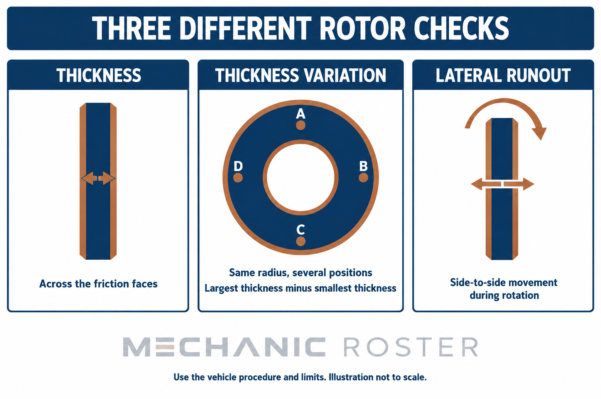
One rotor, three different questions Concept comparison only: thickness is between friction faces; variation compares thickness readings; runout is face movement during rotation. This is not a tool-placement drawing. Use the vehicle-specific procedure for service.
Fictional pad record—not service limits
Position
Inner
Outer
Left front
2.0 mm
6.0 mm
Right front
5.5 mm
5.8 mm
Try it before reading the answer
What conclusion is supported by the pad record, and what should the recommendation avoid?
Worked answer and reasoning
The left-front pads show unequal recorded wear and need investigation against the applicable limits and inspection procedure. The table alone does not prove which component caused it. Avoid promising that replacing pads alone will correct the cause or every reported symptom.
Measure thickness, variation and runoutRead & apply
Rotor thickness is the distance between its friction faces. Thickness variation is the difference between maximum and minimum thickness around specified locations. Lateral runout is side-to-side movement of the installed friction face during rotation. These are separate quantities with different tools, setup and limits. A dial indicator does not replace a thickness micrometer, and a single thickness reading cannot establish variation.
Clean the relevant measuring and mounting surfaces, verify tool zero and resolution, and follow the specified measurement radius and sampling pattern. Avoid a wear lip when the method requires measuring the swept area. Secure the rotor as instructed before runout measurement; record bearing and hub concerns rather than treating every oscillation as rotor-only failure.
Fictional rotor exercise — use actual OEM data on a vehicle
Location
Thickness
A
25.12 mm
B
25.09 mm
C
25.11 mm
D
25.10 mm
Minimum measured = 25.09 mm; maximum = 25.12 mm; variation = 0.03 mm. If the supplied discard limit is 25.00 mm, the readings are above that thickness limit. If the supplied variation limit is 0.02 mm, variation fails. Passing one test does not make the rotor serviceable. A proposed machining operation also needs its own allowed final thickness and other applicable limits.
For drums, compare measured internal diameter and condition with the specified maximum and service instructions. Do not reverse the logic: a rotor has a minimum thickness, while a drum may have a maximum diameter. Include units and specification source in every decision.
Read a measurement as a complete statement
A number needs a quantity, unit, location, method and comparison limit. “25.09” alone cannot establish serviceability. “Left-front rotor minimum measured thickness 25.09 mm at the specified swept locations; applicable minimum 25.00 mm” can be interpreted. Record the source separately so a later reviewer can confirm it applies to the rotor and vehicle. Tool resolution must be fine enough for the criterion being evaluated; a coarse ruler cannot decide a hundredth-of-a-millimeter difference.
Calculate variation from the maximum and minimum of all required readings, not just the first two. For values 25.12, 25.09, 25.11 and 25.10 mm, subtract 25.09 from 25.12. The result is 0.03 mm. The average, 25.105 mm, answers a different question and cannot conceal the lowest reading or the spread. Keep adequate precision through the calculation before reporting to the required precision.
For a dial-indicator exercise, suppose the highest indication is +0.03 mm and the lowest is −0.02 mm. The total indicated movement is 0.05 mm, not 0.01 mm. The sign describes the pointer's direction relative to its zero; the full excursion is the difference between extremes. This does not supply a universal runout limit. Recheck mounting, bearing condition, tool stability and the applicable procedure before assigning that movement to a particular component.
Work thickness, variation and runout separately
A minimum-thickness comparison uses the lowest valid reading, not the mean. A thickness-variation calculation uses the greatest reading minus the least reading at the specified measuring radius. A runout calculation uses the full indicator excursion while the mounted assembly rotates under the prescribed setup. All three quantities may be expressed in millimeters, but they answer different questions. Writing one number under the wrong label can reverse a repair decision.
Use the fictional limits below only for this exercise. The four thickness readings produce a minimum of 25.10 mm and a variation of 0.04 mm. Thus the minimum-thickness comparison passes its stated 25.00 mm floor, while variation fails its 0.03 mm maximum. An assembly can pass one comparison and fail another. Do not average away the failure. If an indicator moves from −0.02 to +0.04 mm, total travel is 0.06 mm, not 0.02 mm.
Training rotor worksheet—fictional values
Item
Reading or supplied limit
Interpretation
A / B / C / D
25.14 / 25.12 / 25.10 / 25.13 mm
Lowest = 25.10 mm
Minimum allowed
25.00 mm
Thickness passes
Maximum variation
0.03 mm
Observed 0.04 mm fails
Indicator extremes
−0.02 to +0.04 mm
Total travel = 0.06 mm
Try it before reading the answer
A second rotor reads 24.98, 25.00, 25.01 and 24.99 mm using the same fictional minimum. Calculate minimum and variation. Would an average of 24.995 mm be an acceptable substitute?
Worked answer and reasoning
Minimum is 24.98 mm and variation is 0.03 mm. The minimum is below 25.00 mm even though variation meets its stated inclusive maximum. The average is not the required comparison. Record each measurement and follow the applicable repair procedure; this worksheet does not determine whether machining or replacement is permitted.
Convert findings into a clear recommendation by separating observed condition, measured value, applicable limit, interpretation and proposed work. Explain what is established and what needs further testing. Pair or axle service decisions must follow the vehicle and component requirements, not an unsupported blanket rule. Obtain authorization for the actual scope, parts and price.
Use the correct service mode, hardware, fastener procedure, fluid and cleanliness controls. Hydraulic work may require a specific bleed sequence or scan-tool routine. Do not substitute a universal sequence for the vehicle instructions. A warning lamp reset does not prove that a hydraulic or mechanical problem was repaired.
Before movement, perform the required static checks for pedal response, fluid level, leaks, assembly security and warning status. Confirm any electronic parking-brake or other initialization requirement. A soft or otherwise abnormal pedal is a reason to stop and investigate, not to hope a road test will correct it. Only conduct an appropriate controlled road check after the vehicle is safe to move.
Give the customer applicable bedding or break-in instructions from the component manufacturer, warranty terms and follow-up guidance. Keep all measurements, approvals and verification results traceable to the job.
Write a repair recommendation someone can approve
Use five connected statements: the finding, the reference, its interpretation, the proposed scope and the verification plan. If a measurement fails, say which criterion failed. If the cause remains unknown, offer the diagnostic step rather than a guaranteed component replacement. Explain associated work, hardware and applicable axle requirements in the estimate. Do not present a partly diagnosed fault as a fixed-price promise to eliminate every symptom.
The finished record should preserve before-and-after evidence. A replacement invoice proves that a part was billed, not that the initial complaint was resolved. A pedal check, leak check, assembly inspection, applicable electronic procedure and safe functional verification answer different questions. Record who performed each required check and any limitations. If verification reveals a new concern, reopen the diagnostic process and obtain the necessary decision before adding work.
Common reporting error
“New brakes; no warranty on noise” does not explain whether a noise was checked. A stronger note states the reported conditions, observations during verification, completed work and any remaining concern. Customer instructions should be the relevant manufacturer guidance, not an invented number of emergency stops or a universal bedding routine. The learner's role is to explain evidence and follow the applicable process, not to invent service procedures from this course.
Close the loop with a before-and-after record
An effective completion record links the original concern, authorized work, corrected findings and final verification. Preserve the initial measurements; do not replace them with the final values. Identify any required assembly, fluid, initialization or bedding procedure from the actual product and vehicle information. There is no universal bedding sequence or torque value in this course.
For a fictional job, the original pulsation is not present during the permitted post-repair check, but a separate low-speed noise remains. The correct record is not “all brake concerns fixed.” State which condition was checked, under what conditions, what improved and what remains unresolved. If the original operating conditions could not safely be reproduced, say so. That limitation informs the next decision and prevents an invoice from becoming a guarantee unsupported by testing.
Delivery evidence
Approved scopeMatch the work to the customer's decision
Final checksRecord the required checks and measurements
Concern checkCompare like operating conditions
HandoffExplain completed work and open concerns
Try it before reading the answer
Write a two-sentence delivery note for the pulsation/noise case without overstating success.
Worked answer and reasoning
“The authorized work and required checks were completed; the reported pulsation was not reproduced during the documented post-repair check. A separate low-speed noise remains and requires the next agreed diagnostic step.” Add the actual conditions, readings, source and authorization details to the repair record.
Case conference: three measurements, three separate decisions
A fictional training worksheet supplies a minimum rotor thickness of 25.00 mm, maximum thickness variation of 0.03 mm and maximum lateral runout of 0.05 mm. Use these limits only for this exercise. The actual job requires its own vehicle-specific procedure, measuring locations and limits.
Case evidence — read before choosing an action
Evidence
Readings
Calculated result
Thickness at comparable radius
25.14 / 25.12 / 25.10 / 25.13 mm
Minimum 25.10 mm
Thickness variation
Maximum minus minimum
25.14 - 25.10 = 0.04 mm
Indicator extremes
-0.02 to +0.04 mm
Total movement 0.06 mm
Work through the decision
A rotor can pass one criterion and fail another. Here the thinnest measured location is above the supplied minimum, but thickness variation exceeds its supplied maximum and total indicated movement exceeds its separate maximum. Averaging the thickness readings hides the thinnest location and does not calculate thickness variation.
Use a suitable brake micrometer to measure between the friction faces at the specified locations, avoiding a wear ridge as instructed. Lateral runout is a different measurement: an indicator follows face movement as the properly secured rotor is rotated. Surface contamination, hub condition, retention method and bearing condition can affect the assembly reading. An unclear tool-contact illustration must not substitute for the service procedure.
A reading outside a limit is evidence requiring a repair decision, not permission to machine automatically. Determine applicable refinishing restrictions and the required finished thickness. Correct mounting problems before condemning a rotor based on assembly runout. After authorized work, repeat the relevant checks and verify the original symptom under safe, appropriate conditions.
Your decision and evidence
Classify each result separately. Explain why a technician should not approve this rotor using only the average thickness or promise that machining will solve the complaint.
Model answer and reasoning
Minimum thickness passes the supplied exercise limit; DTV and runout fail their supplied limits. The average is not the minimum or the max-minus-min variation. Machining eligibility and the cause of assembly runout remain unproven. Record setup, individual readings, references and the proposed next investigation.
Check your work
Keeps thickness, variation and runout separate
Uses total indicator range, including the negative extreme
Write your decision before revealing the model answer. These scenarios and numbers are fictional training examples.
A passing thickness reading is not a passing rotor
A fictional inspection supplies these values: minimum allowed thickness 24.00 mm; maximum allowed variation 0.02 mm; maximum allowed installed runout 0.05 mm. Measurements at the required locations are 24.18, 24.15, 24.17 and 24.16 mm. Installed runout is 0.04 mm. Both inner and outer pads were measured and no hydraulic leak was found in the inspected areas.
Write three separate measurement decisions. Explain why the phrase “rotor passes because it is above minimum” is incomplete. Identify the additional information needed before promising that machining is appropriate. Then write a two-sentence recommendation that keeps the diagnosis separate from a service quotation.
Your evidence, decision and next step:
Compare with the model answer
Minimum thickness is 24.15 mm, above the supplied 24.00 mm limit. Variation is 24.18−24.15 = 0.03 mm, above the supplied 0.02 mm maximum. Runout of 0.04 mm is below the supplied 0.05 mm maximum. The variation criterion fails even though the other two comparisons pass.
Before offering machining, obtain the applicable procedure, permitted final thickness, condition criteria and amount of material that would need removal. The discard limit is not automatically a machining target. A defensible recommendation is: “The measured thickness variation exceeds the supplied limit; minimum thickness and installed runout are within their supplied limits. We recommend the appropriate authorized correction after confirming the permitted service method and final dimensions.” It does not claim that one measurement explains every possible complaint.
Uneven wear and an incomplete explanation
A customer authorizes a brake inspection for a scraping noise. Left-front pad readings are 2 mm inner and 7 mm outer; right-front readings are 6 mm and 6 mm. The technician writes “caliper seized, replace it” without documenting movement checks. The advisor promises the customer this will eliminate all noises. No rotor measurements or final scope approval are recorded.
Identify what is established, what is only a hypothesis, which documentation is missing, and how you would correct the customer update. Draft the next authorized step without promising a specific part or unsafe road test.
Your evidence, decision and next step:
Compare with the model answer
The position-specific readings establish uneven left-front friction wear. They do not uniquely establish the failed component or prove the cause of every sound. The next step is the applicable inspection of caliper operation, hardware and related conditions, plus the remaining required wheel-end measurements. Preserve the original readings and identify the inspection boundaries.
Explain that the initial component statement was premature: “We found uneven wear at the left front. We are checking the mechanism and related conditions before finalizing the repair recommendation.” Obtain approval for any additional diagnostic scope and then for the actual repair. Verification must return to the original complaint conditions when safe, with static checks completed first. Do not mark the vehicle complete solely because new parts have been installed.
Apply it to a job
From the rotor table, calculate minimum thickness and variation. Write separate pass/fail statements using the supplied limits. Create an axle worksheet with inner/outer pad readings, rotor measurements, hose condition, limits and source. Write a recommendation that does not claim an unproven cause. Complete a static-verification checklist before describing a safe road-check plan.
Your evidence and decision
Concern / scenario:
Observation, measurement and reference:
Interpretation and next action:
What remains unknown / who needs to review:
Verification and handoff:
Check your understanding
Explain each item in your own words. Revisit the relevant lesson if you cannot. This self-review is not a practical-skills sign-off.
Explain thickness, variation and runout without using them interchangeably.
Calculate a signed dial-indicator excursion and a thickness spread correctly.
Write position-specific friction and hydraulic findings.
State what evidence would justify the next diagnostic or repair decision.
Create a verification record that distinguishes completed checks from unverified conditions.
Practice before the assessment
Free, ungraded practice. Choose an answer, then check the explanation. These are separate from the final assessment bank.
Further study
Use current vehicle and equipment information for actual service. These public resources informed subject scope and support further learning; Mechanic Roster lessons and questions are original.