Choose safe meter setups, separate open-circuit voltage from loaded performance, and document electrical test conditions.
What you will learn
Select voltage, resistance or current measurement for the question being asked.
Read a simple source–protection–control–load–return circuit.
Calculate and interpret loaded voltage loss using supplied limits.
Record test points and verify a repair under comparable conditions.
Before you start
Low-voltage circuit identification and supervised meter use. This course does not authorize high-voltage work.
How to use this workbook
Read each lesson, work through its example, then answer the practice questions before revealing the explanations. Complete the written exercise before taking the assessment. Numerical examples are fictional training data, not vehicle service specifications.
Open study guideFree lessons for anyone. Print or save a PDF copy.
Plan for approximately 20 minutes of reading and 45 minutes working the examples and exercises. Assessment time is separate.
Course material
Study at your own pace. Open each lesson when you’re ready.
Read the circuit before choosing a testRead & apply
Know the components: the complete circuit
Before using a meter, identify the source, protection, control, load and return in the actual circuit diagram.
Source
Provides potential difference; its voltage can change with operating conditions.
Fuse or circuit protection
Protects the circuit as designed. It is not a repair for an unresolved cause of excessive current.
Switch, relay or electronic driver
Controls operation, sometimes on the return side or by pulsed switching.
Load
Converts electrical energy into another form: light, heat or motion.
Conductors, connectors and return
Complete the operating path. Unwanted resistance can reduce voltage at the load.
Meter and accessories
Measure a selected quantity with a specific connection method; they are not part of the normal operating circuit.
How the parts work together
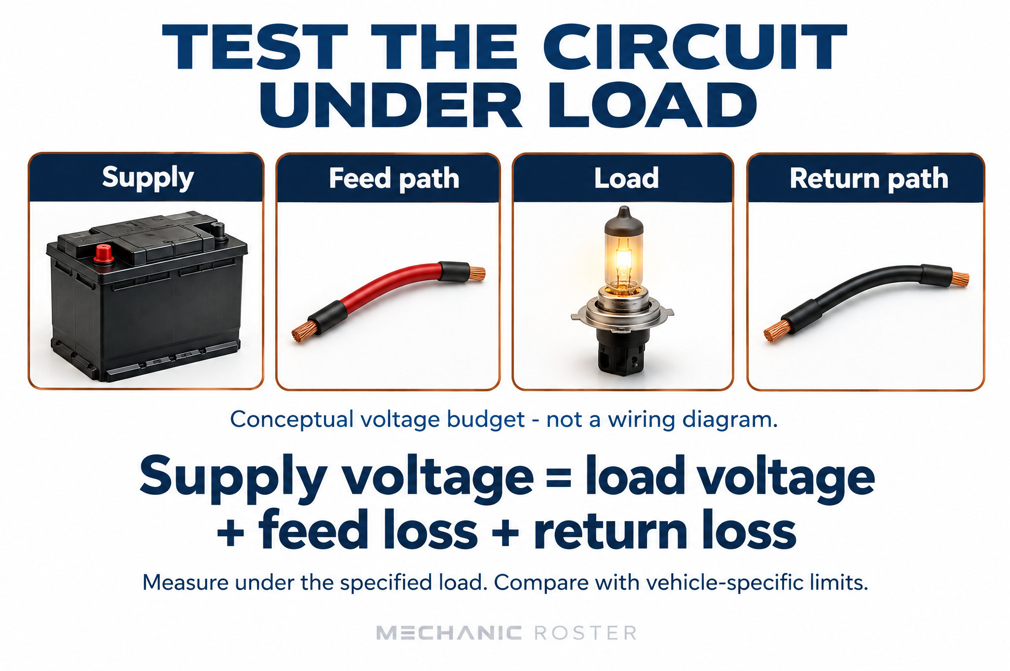
For a simplified steady series circuit, source voltage equals load voltage plus losses along feed and return. Real controlled circuits may switch or pulse; use the specified measurement method rather than applying a simple DC assumption blindly.
Identify and explain
Why must a ground-side switch be identified before interpreting voltage readings?
Check your explanation
Its position changes expected potentials when open or closed. A reading must be interpreted against the real circuit state, not a guessed feed-side arrangement.
Begin with the function that fails and the conditions under which it fails. A window that moves slowly is different from a window that never operates; a lamp that works until a connector is moved suggests an intermittent condition. Record the complaint before deciding which part to replace.
Use the correct wiring diagram to trace source, protection, control, load and return. Mark the connectors, splices and grounds in that path. A ground-side controlled circuit will not behave like a simple power-side switch at every test point. Modules, pulse-width control and shared circuits require the appropriate procedure and test equipment; a basic meter may display an average rather than the full signal.
Identify what each proposed test can prove. Voltage available at an unplugged connector may show a potential difference but not the circuit's ability to carry operating current. Continuity may establish a path at the meter's small test current, but a weak connection may fail under load. A sound plan names the expected result and what a different result would mean.
Do not apply these methods to high-voltage, airbag or other restricted circuits without the relevant qualifications and procedure. A familiar connector shape does not establish that probing is safe.
Voltage, current and resistance answer different questions
Voltage is an electrical potential difference between two points. Current is the rate of charge flow through a path. Resistance opposes that flow. For a simple steady resistive example, voltage equals current multiplied by resistance. A 12 V source across a 6 Ω load produces 2 A in that simplified model. Real motors, electronic controls and changing temperatures can behave differently, so the equation is a reasoning tool, not a substitute for circuit information.
A voltmeter reads between its probes, not “the electricity in a wire.” State both probe locations. A reading between a load's supply terminal and battery negative is not the same measurement as the drop across the load's ground connection. A ground-side-controlled circuit changes the expected potentials according to its switching state. Trace source, protection, switching, load and return before predicting a reading.
Predict before probing
Write what the circuit should do in the test state and what each competing fault would change. If you cannot explain why a chosen pair of points will distinguish two possibilities, the measurement may add a number without reducing uncertainty. Identify the connector pins from the correct diagram and use the specified access method; damaging a terminal while probing can create a new intermittent fault.
Trace a circuit before selecting a meter function
Start with the actual circuit diagram: identify the source, protection, control, load and return. A switch may be on the feed side or the return side, and a controller may operate the circuit intermittently. A voltage that looks unexpected under one assumed arrangement may be normal under the actual arrangement. Draw the complete current path and note the operating state before connecting a tool.
An unloaded connector showing supply voltage establishes a potential difference at those points. It does not prove that the connection can carry the operating current. For example, a high-resistance connection may pass a tiny meter current but lose substantial voltage when a motor runs. A useful plan states the expected result and the next action for each possible result. Do not turn a code description directly into an instruction to replace a module.
The operating circuit is a complete loop Component overview and simplified steady-DC voltage budget, not a connected wiring diagram. No probe positions or meter-jack connections are depicted. Use the vehicle-specific procedure for service.
Try it before reading the answer
An unplugged motor connector reads 12.6 V. List two conclusions that cannot yet be made.
Worked answer and reasoning
You cannot yet conclude that the feed can carry the motor's current or that the motor's return path is satisfactory. The reading also does not establish motor health. Use the actual circuit information to plan a suitable loaded test.
Choose the meter function and connection safelyRead & apply
Voltage is measured across two points, in parallel with the segment of interest. Select the appropriate AC or DC function and input terminals. Inspect leads, probe insulation and meter condition. The meter and accessories must be rated for the task and environment. Protect adjacent terminals from accidental bridging and use approved probing methods rather than forcing a probe into a connector.
Resistance is measured on a de-energized, appropriately isolated circuit under the service procedure. The meter supplies a small test current; external voltage and parallel paths can damage equipment or make the result misleading. A continuity beep is not a universal low-resistance specification. Document lead resistance or compensation where relevant to a small reading.
Current measurement with a series meter changes the circuit path and has input/fuse limits. Never place a meter in current mode directly across a battery or source. A suitable clamp can avoid opening a circuit, but requires correct range, orientation and zeroing, and is not interchangeable with every low-current measurement. Follow the tool's instructions and the vehicle procedure.
This course explains measurement decisions. Live circuit manipulation belongs in supervised practice with the correct tool, protection and procedure.
Choose a measurement configuration deliberately
Voltage measurements generally compare points without opening the circuit. Current measurement may require a suitable clamp or a specifically configured series connection. Resistance measurement uses the meter's own test source and requires the specified de-energized, isolated conditions. These methods are not interchangeable. Connecting a meter's current input across a source can create a dangerous low-resistance path.
Before each change of task, check the function, lead jacks, lead condition, ratings and expected range. Do not assume the previous technician left the meter configured for voltage. A current clamp must be suitable for the signal, correctly oriented and zeroed as required. Multiple conductors carrying opposing currents through the clamp may alter the result. Follow the tool and circuit instructions rather than improvising a connection.
A continuity beep means the meter's threshold was met under its small test current. It does not prove that a path can carry the operating load without excessive loss. An ohmmeter reading can also be affected by parallel paths unless the prescribed isolation is established. Record the test configuration so the result cannot later be mistaken for an operating-load check.
A loaded series circuit voltage budget. This concept illustration is not a wiring or probe-connection diagram.
Separate voltage, resistance and current setups
Voltage is measured between two points. Resistance testing uses the meter's internal source on a de-energized, appropriately isolated circuit. Current measurement requires a suitable series arrangement or a compatible clamp following the equipment instructions. These are different connections, not merely different display units. A lead left in the current jack can create an unsafe low-resistance path when used as if it were a voltage lead.
Before each measurement, confirm the task, function, lead jacks, accessories, expected range and connection method. Inspect leads and use approved adapters that do not spread terminals or damage insulation. For a current clamp, follow its zeroing and positioning instructions. A reading without a valid setup is not reliable merely because it has many decimal places. This low-voltage course does not authorize traction-system testing.
Meter readiness
IdentifyCircuit, operating state and expected quantity
SelectFunction, jacks and suitable accessories
ConnectApproved points and method
InterpretUnits, conditions and applicable reference
Try it before reading the answer
You have just measured current. Before measuring battery voltage, what must you recheck besides the range?
Worked answer and reasoning
Recheck the lead jacks and selected function, as well as lead condition and the approved connection method. A current input is not a voltage input; changing the displayed range alone does not establish a safe setup.
Voltage drop is the potential difference across a circuit segment while the relevant current flows. A resistive connection may show little loss with no load and substantial loss during operation. The test condition therefore belongs beside the reading. Probe placement determines whether you are measuring the load, an entire feed path, a ground path or a single connection.
For a simple DC series circuit, source voltage is distributed across the load and unintended losses. Training example: source 12.4 V, feed-path loss 0.6 V and return-path loss 0.2 V. The load receives approximately 11.6 V. This arithmetic does not create an acceptable limit; compare each segment with the supplied service criterion.
Fictional loaded-circuit exercise
Segment
Reading
Exercise maximum
Feed path
0.60 V
0.20 V
Ground path
0.08 V
0.10 V
The feed path fails the stated limit; the return passes that specific test. Subdivide the feed under the same operating condition to locate the loss. A high reading across a connector identifies loss across that connection; it does not automatically prove the whole harness or module must be replaced.
Ohm's law gives V = I × R. In an exercise, 5 A through 0.1 Ω produces 0.5 V loss. Small resistance can matter at working current. Conversely, a near-zero drop across a path with no current does not prove that path can perform its job. Check operating state and current path before interpreting the number.
Account for voltage around a loaded circuit
In a simplified steady circuit, source voltage is distributed across the load and the losses in its supply and return paths. Suppose a training circuit has 12.0 V at the source, 1.2 V across the supply path, 10.5 V across the load and 0.3 V across the return path. The values sum to 12.0 V. They help locate where voltage is being used, but pass/fail decisions still require the relevant operating conditions and limits.
A useful voltage-drop test measures between the two ends of the suspected section while the relevant current flows. An unloaded reading may be near zero even when a poor connection causes a substantial loss under load. Equally, a near-zero drop is not automatically a good result if the circuit never switched on. Confirm that the intended operating state actually occurred.
Reduce the fault area
If the full supply path shows excessive loss, divide it into meaningful sections using the circuit and safe access points. Compare readings under comparable load. Avoid changing several conditions at once; otherwise a lower number may result from lower current rather than a repaired connection. Keep measurements, test state and the specification together.
Use the voltage budget to localize a loss
For the simplified steady operating circuit below, subtract both path losses from the source voltage to find the voltage across the load. With 12.4 V supply, 0.7 V feed loss and 0.2 V return loss, the remaining load voltage is 11.5 V. The voltage budget describes the measured condition; it does not by itself state which values are acceptable. Acceptability requires the circuit-specific test procedure and limits.
To locate an excessive path loss, subdivide the failing path under comparable operating conditions. If most of the feed loss is across one connector, inspect that connection rather than replacing the entire harness by assumption. A measurement at zero current cannot prove how a resistive path behaves under load. Keep current, temperature and operating command comparable when judging before-and-after results.
Fictional loaded-circuit readings
Quantity
Value
Role
Source
12.4 V
Available potential
Feed path loss
0.7 V
Subtract from source
Return path loss
0.2 V
Subtract from source
Load voltage
11.5 V
12.4 − 0.7 − 0.2
Try it before reading the answer
At 5 A, a resistance of 0.08 Ω causes what voltage loss? If 0.35 V of a 0.40 V feed loss is across one connector, what is the useful next investigation?
Worked answer and reasoning
V=I×R=5×0.08=0.40 V. The connector accounts for most of the measured feed loss, so inspect and test that segment under the proper procedure. The result localizes an observation; it does not automatically prescribe whole-harness replacement.
Document intermittent faults and prove the resultRead & apply
A useful record names the vehicle, symptom, diagram/source, test points, connection method, meter setup, circuit state, load, units, reading and expected range. “Power good” cannot tell another technician whether the connector was unplugged, whether the load was commanded on, or whether the return path was included.
For an intermittent issue, reproduce only safe conditions and record what changes. If a reading changes during controlled harness movement, identify the location, movement and simultaneous symptom. Avoid stretching wires, piercing insulation unnecessarily or pulling connectors under conditions prohibited by the procedure. A movement-sensitive result narrows the investigation; physical inspection and appropriate tests still establish the repair.
After repairing a high-resistance connection, repeat the same loaded test at the same points and verify the affected function. In a training example, feed loss changing from 0.60 V to 0.05 V under comparable load supports improvement; a second reading taken with the load off does not. Check for related faults, correct routing and connector security before closing the job.
If the test is inconclusive, state the limitation and next test. Do not convert an incomplete reading into a confident component diagnosis.
Distinguish a clue from a confirmed cause
A code, symptom or abnormal reading narrows the investigation but may not uniquely identify a part. A low load voltage could arise from supply loss, return loss, source condition or the control state. A normal static result may miss an intermittent condition. Document the temperature, commanded state and load during the failure, then choose a test that can separate the remaining possibilities.
After a repair, repeat the meaningful measurement under comparable conditions. Inspect terminal engagement, routing, protection and strain relief. A connection that works with the harness stretched may fail after reassembly. Confirm relevant system operation and check for faults introduced by the work. Clearing codes is a record-management action, not proof of an electrical repair.
Write the evidence trail
Use a table with test points, circuit state, value, unit, reference and interpretation. Record “not tested” when appropriate. A sentence such as “voltage good” hides whether the reading was at the battery, at the load or across a connection. A useful final note says what changed, how it was verified and whether the original symptom was reproduced after repair.
Make an intermittent-fault record reproducible
For an intermittent concern, record the operating condition, exact test points, tool setup and simultaneous change. “Voltage at connector C dropped during controlled harness movement” is more useful than “bad wiring.” It narrows the search while preserving uncertainty. Do not overstate what a brief normal test proves about a fault that appears only when hot or under vibration.
After a correction, repeat the relevant loaded measurement and function check under comparable conditions. If feed loss drops from 0.40 V to 0.05 V, the change is 0.35 V for that segment and test state. It does not prove every circuit is healthy. Document connector security, routing and any limitations in reproducing the original complaint so the next technician can continue intelligently.
Evidence chain
ConditionReproduce the operating state
ObservationRecord points, units and simultaneous behavior
CorrectionLink work to measured evidence
VerificationRepeat the relevant measurement and function
Try it before reading the answer
Rewrite “all electrical faults fixed” after one connector repair reduced loaded loss from 0.40 to 0.05 V.
Worked answer and reasoning
“Loaded loss across the tested segment decreased from 0.40 to 0.05 V under the documented conditions, and the relevant function was checked.” Add the observed functional result and remaining limitations; do not extend one segment's result to the entire vehicle.
Case conference: a connector that looks normal unloaded
A simplified steady DC circuit supplies a 5 A load. During operation, the supply is 12.4 V, feed-path loss is 0.7 V and return-path loss is 0.2 V. Of the feed loss, 0.6 V is measured across one connector. All numbers are fictional teaching data.
Case evidence — read before choosing an action
Voltage budget
Calculation
Meaning
Feed loss
0.7 V
Includes connector loss
Return loss
0.2 V
Separate path
Load voltage
12.4 - 0.7 - 0.2 = 11.5 V
Across operating load
Connector resistance at this state
0.6 V / 5 A = 0.12 ohm
Inferred from measured drop and current
Work through the decision
Do not subtract the connector loss a second time: it is already part of the 0.7 V feed-path reading. The voltage budget is 0.7 + 11.5 + 0.2 = 12.4 V. Adding a nested measurement as though it were a separate series segment produces a false result. Mark exactly which endpoints each reading spans.
Ohm's law gives an inferred resistance of 0.12 ohm for the connector under the stated condition. That is not a universal acceptable connector value. A small resistance can matter at operating current, while an unloaded voltage reading may look normal. Compare the specified test result to the applicable limit; do not substitute an energized resistance test.
Confirm the function, jacks, leads and connection method before each measurement. A voltmeter is connected between test points; an ohmmeter requires the prescribed de-energized and isolated condition. A current input must not be placed across the source as though it were a voltage input. This example covers conventional low-voltage circuits, not traction-voltage service.
Your decision and evidence
A learner calculates 10.9 V across the load by subtracting the connector's 0.6 V as well. Explain the error and state the evidence needed after a connector repair.
Model answer and reasoning
The learner counted the connector loss twice. Correct load voltage is 11.5 V. After repair, repeat relevant path and function checks under comparable operating conditions, record the exact endpoints and compare with the applicable limits. Improved readings alone do not prove unrelated circuits healthy.
Write your decision before revealing the model answer. These scenarios and numbers are fictional training examples.
The lamp has voltage but is dim
A fictional low-voltage lamp circuit reads 12.4 V at its source. With the lamp operating, the supply path drops 1.6 V, the lamp drops 10.5 V and the return path drops 0.3 V. The exercise supplies a maximum supply-path loss of 0.4 V under these conditions. With the lamp disconnected, its supply terminal reads 12.4 V relative to source negative.
Explain why the disconnected reading does not clear the supply path. Check the arithmetic, identify the supported fault area and propose the next measurement. Do not name a particular connector without evidence.
Your evidence, decision and next step:
Compare with the model answer
The loaded values sum to 12.4 V. The supply path exceeds its fictional 0.4 V limit; the unloaded terminal reading does not test its performance under operating current. Segment the supply path using the diagram and suitable access points, keeping the operating load comparable. The result supports excess loss somewhere in that path, not an automatic lamp or connector replacement. After the identified fault is corrected, repeat the loaded measurements and verify operation. Use actual vehicle criteria on a real job.
A continuity beep is offered as proof
A blower intermittently stops when warm. A disconnected wire passes a continuity check while cold. A teammate concludes that the harness and connections are good and orders a motor. No loaded tests, temperature notes or control-state checks were recorded.
List the unsupported conclusion, the missing test conditions and the evidence you would seek before recommending a component. Explain the limits of the existing reading without saying it was entirely useless.
Your evidence, decision and next step:
Compare with the model answer
The continuity result establishes only what the meter observed under that cold, low-current configuration. It does not establish warm loaded performance or the command state during the failure. Reproduce the relevant condition safely, confirm whether the blower is being commanded to operate, and evaluate the supply, return and load response with the applicable procedure. The cold continuity result remains a valid limited observation. Replacing the motor before discriminating these possibilities is a hypothesis-driven purchase, not a confirmed diagnosis.
Apply it to a job
Draw a battery, protection, control, load and return path. Mark parallel voltage-probe locations without drawing a current meter across the source. Calculate 12.4−0.6−0.2. Use the exercise limits to choose which path to subdivide. Complete a blank test record and write a comparable post-repair test. Use diagrams or a supervised training board, not an unfamiliar live vehicle.
Your evidence and decision
Concern / scenario:
Observation, measurement and reference:
Interpretation and next action:
What remains unknown / who needs to review:
Verification and handoff:
Check your understanding
Explain each item in your own words. Revisit the relevant lesson if you cannot. This self-review is not a practical-skills sign-off.
Explain what each meter function measures.
Name both probe locations and the circuit state for a reading.
Use a simple voltage balance without inventing a universal service limit.
Distinguish continuity from loaded performance.
Write a before/after electrical test record.
Practice before the assessment
Free, ungraded practice. Choose an answer, then check the explanation. These are separate from the final assessment bank.
Further study
Use current vehicle and equipment information for actual service. These public resources informed subject scope and support further learning; Mechanic Roster lessons and questions are original.